JPEG Hardware Compressor
Description
This project features a complete JPEG Hardware Compressor (standard
Baseline DCT, JFIF header) with 2:1:1 subsampling, able to compress at
a rate of up to 24 images per second (on XC2V1000-4 @ 40 MHz with
resolution 352x288).
Image resolution is not limited. It takes an RGB input (row-wise)
and outputs to a memory the compressed JPEG image. Its quality is
comparable to software solutions.
A testbench has been made that
takes a bitmap image from your computer and writes a compressed JPEG
file by simulating the code. Download the code and try it, it's easy.
The
source code is VHDL and it is LGPL, so it can be used in commercial
applications as long as the terms of the license are respected.
Anyone interested in the image standards used in this project, they can be downloaded from the following places:
JPEG (ITU-T81 standard): http://www.w3.org/Graphics/JPEG/itu-t81.pdf
JFIF (JPEG file headers): http://www.w3.org/Graphics/JPEG/jfif3.pdf
BMP (bitmaps for the testbench): http://netghost.narod.ru/gff/vendspec/micbmp/bmp.txt
For any questions
email me.
Features
- JPEG (ISO standard compliant and ITU-T81 compliant)
- Baseline DCT
- Huffman Encoding
- JFIF Header
- Three quantization (compression) levels
- Hardware resources (included in source)
- Xilinx Coregen DCT core (2D Forward DCT)
- SP BlockRAM memories (11, not counting memory for final compressed image)
- Total LUTs: 3969 (38% of XC2V1000-4)
- Clock Freq: 41.2 MHz for XC2V1000-4
Status
- 13/Jul/2007 : Project posted at Sourceforge.net
- 14/Mar/2005 : New directory structure for source files.
Updated source code thanks to Peter Eisemann to include fixes to allow
correct simulation under ModelSim. (Functionality has not changed).
- 03/Jan/2005 : Project posted at Opencores.org
JPEG Hardware Compressor: Detailed Description
Notes
Some quick notes until the time I upload the full documentation:
- This
implementation is compliant with ISO standard (and ITU standard T-81),
it features a compliant JPEG compressor Baseline DCT with Huffman
encoding and 2x2 1x1 1x1 subsampling. The header is the widely employed
JFIF. Baseline DCT JPEG with JFIF header is one of the most used image
formats.
- Included with the source code is a Testbench which allows you
to compress a bitmap (uncompressed 24 bit BMP) file located in the
project folder (if using Active-HDL then in the design folder) just by
simulating it. Its name MUST be "image.bmp". By the way, remember that
a bitmap image stores the information bottom up, and JPEG is
top-bottom, so you should flip (invert) the bitmap image (see the test
image if you don't understand what I mean). This is only important for
simulation.
- The testbench is made in such a way that it will
automatically exit the simulation when it finishes. A 352x288 image
takes almost 40 ms of simulation time (that will take some minutes
depending on your machine). The output image will be in the same folder
as "image.bmp" and its name will be "image.jpg" (it will overwrite
previous outputs without warning).
- It has been simulated on Windows machines, so I can't
guarantee anything on simulation over Linux though I don't think there
could be any problem at all. Please update me on this.
- It has been synthesized and tested in a Xilinx Virtex-2
XC2V1000-4 running at 40 MHz (that is why it takes 40 ms, the testbench
simulates a 40 MHz clock). This is one of the worst speed grades (-4),
so with most other FPGAs you will get faster implementations.
- It uses at minimum 11 BlockRAMs (one of them for the DCT
block), but you will need some more to store the final compressed image
(whose size varies as compression depends on the image as well as in
the compression level), the source code in the Downloads page includes
a memory for this purpose of 51.200 bytes (buffer_img), that is 25
BlockRAMs.
- There is an easily overridable limitation on input image
resolution, for a description on how to change the maximum input image
size see the Notes at the beginning of the main source file
"compressor.vhd".
- The only real limitation is that the input image must have
width and height multiple of 16 (that is, an image 32x32 will produce a
strictly compliant JPEG image file, but not a 32x24 or a 24x32 input
image, although the resulting image will more likely still be
viewable), this is due to the subsampling method employed. This
limitation could be overriden with some extra logic (for padding as
indicated in the JPEG standard).
- Finally I would like to apologize if you find this code
somewhat messy. When I programmed it, I imposed myself very strict
deadlines and making it opensource was not in my mind, mainly because,
if I were to do it again, I would do it in other way to get much more
performance. The main problem faced with this implementation was a very
scarce availability of BlockRAM in the target FPGA, so some areas that
could perfectly run in parallel, speeding a lot the whole process, had
to be made sequential in order to save up BlockRAMs. Anyways, this code
works (it functioned as a webcam, attached to a CMOS sensor) and,
though not as fast as it could be, it has a good performance. This
source code is LGPL. Any questions, suggestions, comments (positive
criticism) is always welcome.
Functional Description
The source code is composed of 9 VHDL files:
- compressor_tb.vhd
: Testbench file for the project. It reads an uncompressed BMP located
in the project folder (not necessarily the source code folder) and
outputs a JPG compressed image (the actual writing of the output file
is carried out by the next file).
- compressor.vhd : This is the main code file. Inside, there are
a few concurrent instructions, declarations of the needed componentes
(BlockRAMs and DCT block) and two processes which are responsible of
the whole compression process. To better follow the next explanation
consult the figure located after this explanation. The first process is
RGB2YCbCr is in charge of converting the input signals (Red, Green and
Blue, strobed by ProcessRGB signal) to the YCbCr color space and to
apply a level shift as specified by the JPEG standard. The second is
the process JPEG, it feeds the DCT block (DCT-2D Core in the figure)
with data from the previous process (the interface between the two
processes are three memories (Y, Cb and Cr Compression Buffers in the
figure), one for luminance (Y) data, one for blue chrominance (Cb) and
another for red chrominance (Cr)); after the DCT has processed the data
(calculated the Forward 2D-DCT) it is quantized with the values stored
in memory q_rom (Q ROM in the figure). As this quantization implies
dividing by an integer number (remember that only divisions by power of
2 numbers and multiplications times an integer can be made really
efficient in digital logic thru the use of shifts, right for division,
left for multiplication), the solution was to convert the number to
divide into a fraction with denominator 16384 for all the quantization
values (128 for every compression level and there are three of these)
so that we can multiply times an integer (left shift and some
additions) and divide by a power of 2 number (right shift). For
instance: to divide by 11 is the same as multiplying times 1/11, which
is almost the same as multiplying times 1489/16384, which is actually
equal to dividing by 11.003357. Using this apparently complicated way
of handling real number operations we get the fastest implementation
and no floating point, only a minimal error (you would never notice the
visual difference). After quantization of all the values, Huffman
encoding starts by looking up the tables stored in huff_rom (Huffman
ROM in the figure) and storing in the final image buffer the compressed
image (should be buffer_img but in the figure is left as a blue upwards
pointing arrow). By the way, at the beginning, when a compression level
is selected and the port CompressImage signals the start of a new
image, the header in buffer_img (yes, there are some hundred bytes
pre-stored with the fixed fields in the header) is updated with image
dimensions and with the quantization tables for the selected
compression (they are read from the ROM tabla_q in the figure and
copied to the appropiate location in buffer_img).
- buffer_img.vhd : CoreGen generated file with wrapper for the 25
SP BlockRAMs, Read/Write, WidthxDepth = 8 bits x 51200, where final
image is stored.
- buffer_comp.vhd : CoreGen generated file with wrapper for 5 SP
BlockRAMs, Read/Write, WidthxDepth = 12 bits x 5632. Y pixels (8 bits)
stored here and also, after transformation by DCT, their quantized
counterparts (12 bits) are stored over them.
- buffer_comp_chrom.vhd : CoreGen generated file with wrapper for
1 SP BlockRAM, Read/Write, WidthxDepth = 12 bits x 1408. This component
is instantiated twice, one for Cb pixels, and other for Cr pixels. Cx
pixels (8 bits) stored here and also, after transformation by DCT,
their quantized counterparts (12 bits) are stored over them.
- huff_rom.vhd : CoreGen generated file with wrapper for 1 SP
BlockRAM, Read Only, WidthxDepth = 20 bits x 352. Huffman Code Tables
stored here.
- q_rom.vhd : CoreGen generated file with wrapper for 1 SP
BlockRAM, Read Only, WidthxDepth = 13 bits x 384. Quantization
Numerators stored here for multiplication and later division by 16384
as explained above. Three compression levels, two tables for each one
(AC and DC), 64 elements in each one : 3x2x64=384.
- tabla_q.vhd : CoreGen generated file with wrapper for 1 SP
BlockRAM, Read Only, WidthxDepth = 8 bits x 384. Quantization Tables
stored here for updating of the final JPEG file header. Three
compression levels, two tables for each one (AC and DC), 64 elements in
each one : 3x2x64=384.
- dct2d.vhd : CoreGen generated file with wrapper for 2-D
Discrete Cosine Transform (Forward DCT), Data Width = 8 bits Signed,
Coefficients Width = 24 (Enable Symmetry), Precision Control: Round,
Internal Width: 19, Result Width: 19, Performance: Clock Cycles per
input=9, Transpose Memory = Block, Reset: No. (Results: Latency = 95
cycles, Row Latency = 15 cycles, Column Latency = 15 cycles). Takes as
input sixty-four 8 bits signed values and outputs sixty-four 19 bits
signed numbers in the frequency domain (the LSBs are decimals).
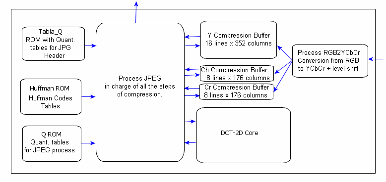
JPEG HW Compressor Block Diagram
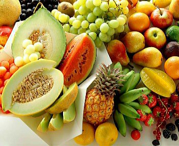
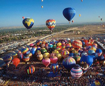
Output Images
Here are some examples of compressed images outputted by the Compressor.
The compressor has in ROM three different quantization tables which
allow it to output images with three different compression/quality
levels.

Input image (297 KB uncompressed)
Output Image (39.7 KB Low Compression Q15)

Output Image (19.6 KB Medium Compression Q31=ITU Standard Compression)

Output Image (10.0 KB High Compression Q50)
Comparisons
Here we have two comparisons:
- First,
a compressed image without subsampling and one with the subsampling
used by the HW JPEG Compressor (2:1:1). The visual difference is not
noticeable, but size reduction is.
- Second, an image compressed with the same quantization tables
(Q15) first by the commercial software Paint Shop Pro 8 and then by
this HW JPEG Compressor. There exists a minimum difference in chroma
treatment (notice it around the smaller balloons). This project follows
the recommendation of the standard when subsampling (average pixels).
It could be due to an enhanced subsampling method, I am open to
suggestions...

Without subsampling (20.8 KB, as many chroma pixels as luminance pixels)
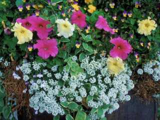
2:1:1 Subsampling (16.8 KB, for every 4 luminance pixels, only one for red chroma and one for blue chroma)
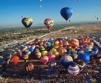
JPEG Image Outputted by PSP8 (38.2 KB, Q15)
JPEG Image Outputted by JPEG HW Compressor (38.4 KB, Q15)